2013 Chevy Alternator Question

  • FishBlood&RiverMud
    Prescott
    Posts: 6687
    #1783238

    2013 Chevrolet Silverado 1500 5.3L 70k

    Road trip today I notice my voltage is low. I monitored closely thereafter, 10 to 20 minutes later voltage climbs back to normal. Holds there for a while, then drops again and holds there.

    What’s up? Voltage regulator in alternate going bad?

    Do I need to fix ASAP or will it wait a few hundred miles when I’m back home after the weekend?

    Thanks

    grubson
    Harris, Somewhere in VNP
    Posts: 1350
    #1783239

    I’m pretty sure that what your explaining is normal. Its a computer controlled alternator. If the electrical load is low it will shut off periodically until voltage gets low enough then it will turn back on. Both of the gm trucks I own do it.

    grubson
    Harris, Somewhere in VNP
    Posts: 1350
    #1783240

    I forgot to ask if the red battery light is/ was on? If your charging system stops working that light will come on almost immediately.

    Iowaboy1
    Posts: 3661
    #1783241

    you may have a battery going bad and eating up all of the extra juice the alternator is putting out,hence the low readings and normal readings.
    yes,the alternator is computer controlled but it should be showing full voltage all of time,especially when running the air conditioner.

    cant remember if that truck use the Valeo brand of alternator or not,if it does they usually arent worth rebuilding and you end up buying new.
    if you take it to the shop and the battery tests good,have them scan the computer to see if the computer is turning the “L” terminal on and off normally,if it is the alternator is bad,have that verified with a load test.

    good luck fishblood!! I know you dont need any troubles with a holiday coming up !!

    munchy
    NULL
    Posts: 4729
    #1783242

    Was the needle in the red or was it still in the middle (white?) color? My ‘16 does the same but stays in the white. White should be normal operation. Red is not.

    FishBlood&RiverMud
    Prescott
    Posts: 6687
    #1783259

    No warning lights or anything.
    I was driving with Windows open and no a/c.

    One picture showing it at low. Other normal.

    Attachments:
    1. CameraZOOM-20180629110239875.jpg

    2. CameraZOOM-20180629110900213.jpg

    munchy
    NULL
    Posts: 4729
    #1783264

    Perfectly normal. It’s the on demand charging system working as designed.

    Iowaboy1
    Posts: 3661
    #1783267

    Perfectly normal. It’s the on demand charging system working as designed.

    munchy no disrespect intended,the voltage should never show below a fully charged batteries voltage.
    the pic shows around eight volts,these newer systems need a minimum of twelve point six volts to operate correctly.
    remember,you are supplying the engines computer and all of its monitored components,a body module that monitors the abs system,windows,lights,seat belts,a/c,etc.
    add the transmission controller and its functions,many speed sensors,shift solenoids,,if it is 4×4,add the transfer case and the front diff,,etc.

    these systems demand the best the battery and alternator can put out all of the time every time.
    bad grounds,faulty gauges,bad batteries,poor connections anywhere can affect the volt meters readings,it needs checked out.

    after all of that and no intention to derail the thread,whatcha been cooking lately Munchy???

    404 ERROR
    MN
    Posts: 3918
    #1783269

    On the bright side, your thermostat works great!

    B-man
    Posts: 5424
    #1783271

    <div class=”d4p-bbt-quote-title”>Munchy wrote:</div>
    Perfectly normal. It’s the on demand charging system working as designed.

    munchy no disrespect intended,the voltage should never show below a fully charged batteries voltage.
    the pic shows around eight volts,these newer systems need a minimum of twelve point six volts to operate correctly.
    remember,you are supplying the engines computer and all of its monitored components,a body module that monitors the abs system,windows,lights,seat belts,a/c,etc.
    add the transmission controller and its functions,many speed sensors,shift solenoids,,if it is 4×4,add the transfer case and the front diff,,etc.

    these systems demand the best the battery and alternator can put out all of the time every time.
    bad grounds,faulty gauges,bad batteries,poor connections anywhere can affect the volt meters readings,it needs checked out.

    after all of that and no intention to derail the thread,whatcha been cooking lately Munchy???

    No disrespect, but where do you see 8 volts???

    The lowest reading on the gauge is 9 volts (stone dead battery), and the needle isn’t anywhere near it.

    To the op, I wouldn’t worry a out a thing, unless you think it’s a new issue.

    I had a 2013 5.3 Silverado and remember seeing the gauge move around as needed.

    Iowaboy1
    Posts: 3661
    #1783273

    <div class=”d4p-bbt-quote-title”>iowaboy1 wrote:</div>

    <div class=”d4p-bbt-quote-title”>Munchy wrote:</div>
    Perfectly normal. It’s the on demand charging system working as designed.

    munchy no disrespect intended,the voltage should never show below a fully charged batteries voltage.
    the pic shows around eight volts,these newer systems need a minimum of twelve point six volts to operate correctly.
    remember,you are supplying the engines computer and all of its monitored components,a body module that monitors the abs system,windows,lights,seat belts,a/c,etc.
    add the transmission controller and its functions,many speed sensors,shift solenoids,,if it is 4×4,add the transfer case and the front diff,,etc.

    these systems demand the best the battery and alternator can put out all of the time every time.
    bad grounds,faulty gauges,bad batteries,poor connections anywhere can affect the volt meters readings,it needs checked out.

    after all of that and no intention to derail the thread,whatcha been cooking lately Munchy???

    No disrespect, but where do you see 8 volts???

    The lowest reading on the gauge is 9 volts (stone dead battery), and the needle isn’t anywhere near it.

    To the op, I wouldn’t worry a out a thing, unless you think it’s a new issue.

    I had a 2013 5.3 Silverado and remember seeing the gauge move around as needed.

    I understand your question as the gauge clearly has a nine volt low side and a nineteen volt high side.
    I am going by what the voltage reading is by what it is reading below fourteen volts,if you divide the lines by quarters of the gauge,it is showing around eight volts in its operating range or close to it.
    I have been at this long enough to know that factory gauges are only a guideline regardless of what the dial says.

    and you are correct,if battery voltage is too low,it should not run,however,if the alternator is doing its job,it will continue to run as the voltage is there to make sure it does,but,the gauge can only show what the battery is putting out while it is sucking up excess voltage from the alternator due to an internal short while it keeps running,hope that makes sense.

    in other words,if the battery is okay,the gauge will show the excess the alternator is generating,this is where you will see the higher readings,ie,fourteen volts and above.
    sorry,I am not a teacher and cant explain how I understand things,sure wish I could.

    nhamm
    Inactive
    Robbinsdale
    Posts: 7348
    #1783280

    My last Tahoe and Yukon has always done that. My research into also what munchy eluded to.

    munchy
    NULL
    Posts: 4729
    #1783284

    munchy no disrespect intended,the voltage should never show below a fully charged batteries voltage.

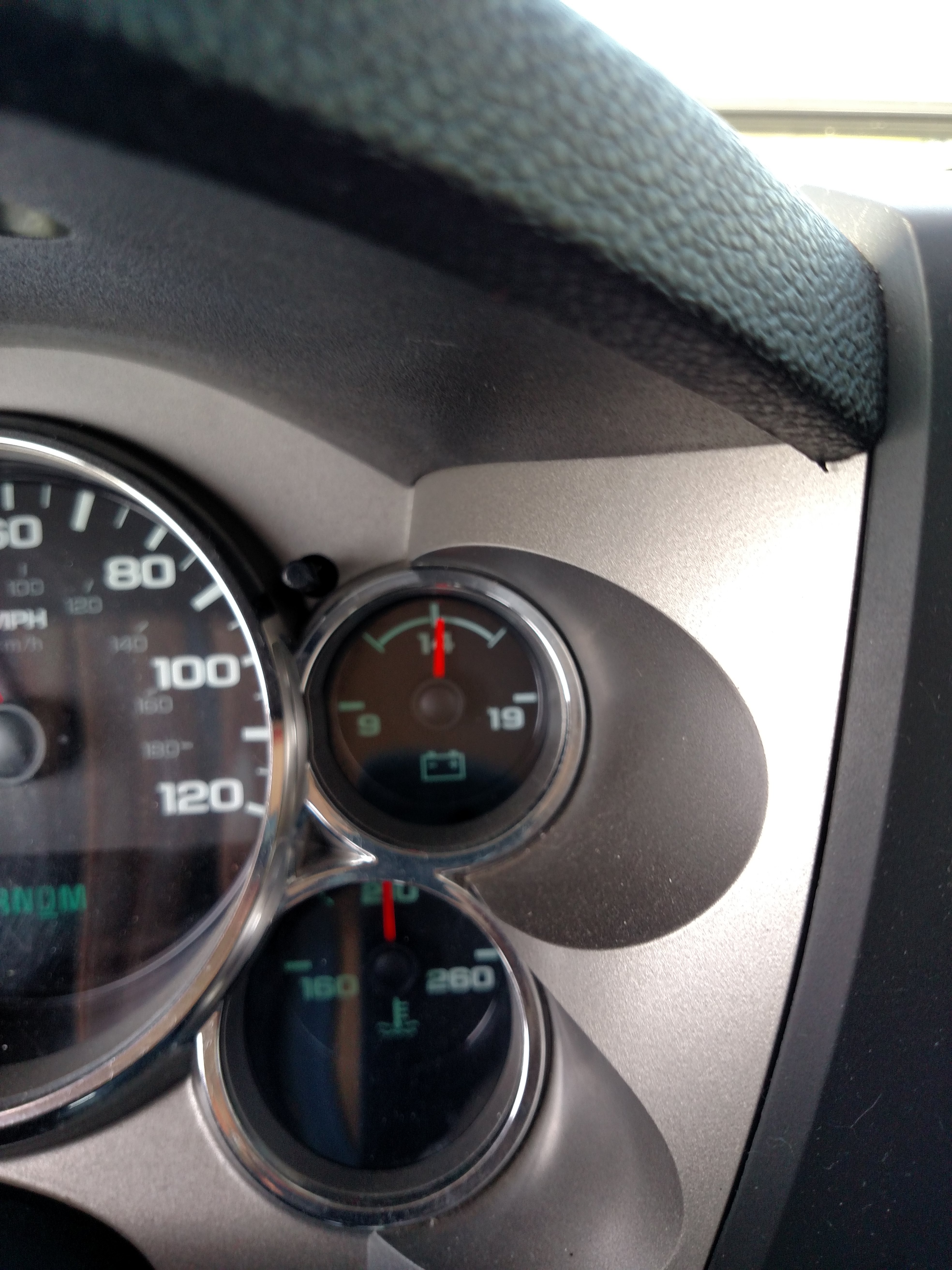
    That gauge in the pic is reading around 13volts. Like I said, it’s how the system was designed. When I first got my truck a few months back I noticed the exact same thing, did a little googlin and found the internet is full of threads just like this one. As long as there are no warning lights and it stays between the white marks you are good.

    A little light readin….

    Charging System Description and Operation

    Electrical Power Management
    Overview

    The electrical power management system is designed to monitor and control the
    charging system and send diagnostic messages to alert the driver of possible
    problems with the battery and generator. This electrical power management system
    primarily utilizes existing on-board computer capability to maximize the
    effectiveness of the generator, to manage the load, improve battery
    state-of-charge and life, and minimize the system’s impact on fuel economy. The
    electrical power management system performs 3 functions:
    It monitors the battery voltage and estimates the battery condition.

    It takes corrective actions by boosting idle speeds, and adjusting the
    regulated voltage (if equipped).

    It performs diagnostics and driver notification.

    The battery condition is estimated during ignition-off and during
    ignition-on. During ignition-off the state-of-charge of the battery is
    determined by measuring the open-circuit voltage. The state-of-charge is a
    function of the acid concentration and the internal resistance of the battery,
    and is estimated by reading the battery open circuit voltage when the battery
    has been at rest for several hours.

    The state-of-charge can be used as a diagnostic tool to tell the customer or
    the dealer the condition of the battery. Throughout ignition-on, the algorithm
    continuously estimates state-of-charge based on adjusted net amp hours, battery
    capacity, initial state-of-charge, and temperature.

    While running, the battery degree of discharge is primarily determined by a
    battery current sensor (if equipped), which is integrated to obtain net amp
    hours.

    If equipped with a battery current sensor, the electrical power management
    function is also designed to perform regulated voltage control to improve
    battery state-of-charge, battery life, and fuel economy. This is accomplished by
    using knowledge of the battery state-of-charge and temperature to set the
    charging voltage to an optimum battery voltage level for recharging without
    detriment to battery life.

    The Charging System Description and Operation is divided into 3 sections. The
    first section describes the charging system components and their integration
    into the electrical power management. The second section describes charging
    system operation. The third section describes the instrument panel cluster
    operation of the charge indicator, driver information center messages, and
    voltmeter operation.

    Charging System Components

    Generator

    The generator is a serviceable component. If there is a diagnosed failure of
    the generator it must be replaced as an assembly. The engine drive belt drives
    the generator. When the rotor is spun it induces an alternating current (AC)
    into the stator windings. The AC voltage is then sent through a series of diodes
    for rectification. The rectified voltage has been converted into a direct
    current (DC) for use by the vehicles electrical system to maintain electrical
    loads and the battery charge. The voltage regulator integral to the generator
    controls the output of the generator. It is not serviceable. The voltage
    regulator controls the amount of current provided to the rotor. If the generator
    has field control circuit failure, the generator defaults to an output voltage
    of 13.8 V.

    Body Control Module (BCM)

    The body control module (BCM) is a GMLAN device. It communicates with the
    engine control module (ECM) and the instrument panel cluster for electrical
    power management (electrical power management) operation. The BCM determines the
    output of the generator and sends the information to the ECM for control of the
    generator turn on signal circuit. It monitors the generator field duty cycle
    signal circuit information sent from the ECM for control of the generator. It
    monitors a battery current sensor (if equipped), the battery positive voltage
    circuit, and estimated battery temperature to determine battery state of charge.
    The ECM performs idle boost.

    Battery Current Sensor (if equipped)

    The battery current sensor is a serviceable component that is connected to
    the negative battery cable at the battery. The battery current sensor is a
    3-wire hall effect current sensor. The battery current sensor monitors the
    battery current. It directly inputs to the BCM. It creates a 5-volt pulse width
    modulation (PWM) signal of 128 Hz with a duty cycle of 0–100 percent. Normal
    duty cycle is between 5–95 percent. Between 0–5 percent and 95–100 percent are
    for diagnostic purposes.

    Engine Control Module (ECM)

    When the engine is running, the generator turn-on signal is sent to the
    generator from the ECM, turning on the regulator. The generator’s voltage
    regulator controls current to the rotor, thereby controlling the output voltage.
    The rotor current is proportional to the electrical pulse width supplied by the
    regulator. When the engine is started, the regulator senses generator rotation
    by detecting AC voltage at the stator through an internal wire. Once the engine
    is running, the regulator varies the field current by controlling the pulse
    width. This regulates the generator output voltage for proper battery charging
    and electrical system operation. The generator field duty terminal is connected
    internally to the voltage regulator and externally to the ECM. When the voltage
    regulator detects a charging system problem, it grounds this circuit to signal
    the ECM that a problem exists. The ECM monitors the generator field duty cycle
    signal circuit, and receives control decisions based on information from the
    BCM.

    Instrument Panel Cluster

    The instrument panel cluster provides the customer notification in case a
    concern with the charging system. There are 2 means of notification, a charge
    indicator and a driver information center message of SERVICE BATTERY CHARGING
    SYSTEM if equipped.

    Charging System Operation

    The purpose of the charging system is to maintain the battery charge and
    vehicle loads. There are 6 modes of operation and they include:
    Battery Sulfation Mode

    Charge Mode

    Fuel Economy Mode

    Headlamp Mode

    Start Up Mode

    Voltage Reduction Mode

    The engine control module (ECM) controls the generator through the generator
    turn ON signal circuit. The ECM monitors the generator performance though the
    generator field duty cycle signal circuit. The signal is a pulse width
    modulation (PWM) signal of 128 Hz with a duty cycle of 0–100 percent. Normal
    duty cycle is between 5–95 percent. Between 0–5 percent and 95–100 percent are
    for diagnostic purposes. The following table shows the commanded duty cycle and
    output voltage of the generator:

    Commanded Duty Cycle

    Generator Output Voltage

    10%

    11 V

    20%

    11.56 V

    30%

    12.12 V

    40%

    12.68 V

    50%

    13.25 V

    60%

    13.81 V

    70%

    14.37 V

    80%

    14.94 V

    90%

    15.5 V

    The generator provides a feedback signal of the generator voltage output
    through the generator field duty cycle signal circuit to the ECM. This
    information is sent to the body control module (BCM). The signal is PWM signal
    of 128 Hz with a duty cycle of 0–100 percent. Normal duty cycle is between
    5–99 percent. Between 0–5 percent and 100 percent are for diagnostic purposes.

    Battery Sulfation Mode

    The BCM will enter this mode when the interpreted generator output voltage is
    less than 13.2 V for 45 minutes. When this condition exists the BCM will enter
    Charge Mode for 2–3 minutes. The BCM will then determine which mode to enter
    depending on voltage requirements.

    Charge Mode

    The BCM will enter Charge Mode when ever one of the following conditions are
    met.
    The wipers are ON for than 3 seconds.

    GMLAN (Climate Control Voltage Boost Mode Request) is true, as sensed by the
    HVAC control head. High speed cooling fan, rear defogger and HVAC high speed
    blower operation can cause the BCM to enter the Charge Mode.

    The estimated battery temperature is less than 0°C (32°F).

    Battery State of Charge is less than 80 percent.

    Vehicle speed is greater than 145 km/h (90 mph)

    Battery current sensor fault exists (if equipped).

    System voltage was determined to be below 12.56 V

    When any one of these conditions is met, the system will set targeted
    generator output voltage to a charging voltage between 13.9–15.5 V, depending on
    the battery state of charge and estimated battery temperature.

    Fuel Economy Mode

    The BCM will enter Fuel Economy Mode when the estimated battery temperature
    is at least 0°C (32°F) but less than or equal to 80°C (176°F), the calculated
    battery current is less than 15 amperes and greater than −8 amperes, and the
    battery state-of-charge is greater than or equal to 80 percent. Its targeted
    generator output voltage is the open circuit voltage of the battery and can be
    between 12.5–13.1 V. The BCM will exit this mode and enter Charge Mode when any
    of the conditions described above are present.

    Headlamp Mode

    The BCM will enter Headlamp Mode when ever the headlamps are ON (high or low
    beams). Voltage will be regulated between 13.9–14.5 V.

    Start Up Mode

    When the engine is started the BCM sets a targeted generator output voltage
    of 14.5 V for 30 seconds.

    Voltage Reduction Mode

    The BCM will enter Voltage Reduction Mode when the calculated ambient air
    temperature is above 0°C (32°F). The calculated battery current is less than
    1 ampere and greater than −7 amperes, and the generator field duty cycle is less
    than 99 percent. Its targeted generator output voltage is 12.9 V. The BCM will
    exit this mode once the criteria are met for Charge Mode.

    Auxiliary Battery
    Charging (TP2)

    The auxiliary battery provision (TP2) can be used to supply electrical power
    to additional equipment that the customer may choose to add, such as a slide-in
    camper or trailer, without discharging the vehicles primary battery. The
    auxiliary battery relay closes when the engine is running, in order to allow the
    generator to charge the auxiliary battery. The relay opens when the engine is
    off, so that the accessories will not discharge the vehicles primary battery,
    which is used for engine starting. If the vehicle is equipped with an auxiliary
    battery, the relay will be located on the driver’s side of the vehicle, next to
    the underhood electrical center. Generally, a fuse should not be used in the
    STUD 1 Fuse 68 position of the underhood fuse block, if the vehicle is equipped
    with an auxiliary battery. A plastic plug may be installed in this position
    instead of a fuse. If a fuse is installed in this position, the accessories will
    discharge the primary battery in addition to the auxiliary battery.

    Instrument Panel Cluster
    Operation

    Charge Indicator Operation

    The instrument panel cluster illuminates the charge indicator and displays a
    warning message in the driver information center if equipped, when the one or
    more of the following occurs:

    The engine control module (ECM) detects that the generator output is less
    than 11 V or greater than 16 V. The instrument panel cluster receives a GMLAN
    message from the ECM requesting illumination.

    The instrument panel cluster determines that the system voltage is less than
    11 V or greater than 16 V for more than 30 seconds. The instrument panel cluster
    receives a GMLAN message from the body control module (BCM) indicating there is
    a system voltage range concern.

    The instrument panel cluster performs the displays test at the start of each
    ignition cycle. The indicator illuminates for approximately 3 seconds.

    Display Message: BATTERY NOT CHARGING SERVICE CHARGING SYSTEM or SERVICE
    BATTERY CHARGING SYSTEM

    The BCM and the ECM will send a serial data message to the driver information
    center for the BATTERY NOT CHARGING SERVICE CHARGING SYSTEM or SERVICE BATTERY
    CHARGING SYSTEM message to be displayed. It is commanded ON when a charging
    system DTC is a current DTC. The message is turned OFF when the conditions for
    clearing the DTC have been met. During cold weather warm-up and extreme
    electrical demand , the generator capacity can be briefly exceeded causing this
    message to be displayed for up to two minutes

    after all of that and no intention to derail the thread,whatcha been cooking lately Munchy???

    Unfortunately nothing, been too busy working and selling my house. Which once I receive the contract today will be sold. yay

    Denny O
    Central IOWA
    Posts: 5727
    #1783328

    What the hell was that?

    Eelpoutguy
    Farmington, Outing
    Posts: 10030
    #1783354

    Alex,
    I’ll take alternators for 100 please.

    munchy
    NULL
    Posts: 4729
    #1783359

    What the hell was that?

    Shortened version…

    Voltage Reduction Mode

    The BCM will enter Voltage Reduction Mode when the calculated ambient air
    temperature is above 0°C (32°F). The calculated battery current is less than
    1 ampere and greater than −7 amperes, and the generator field duty cycle is less
    than 99 percent. Its targeted generator output voltage is 12.9 V. The BCM will
    exit this mode once the criteria are met for Charge Mode.

    FishBlood&RiverMud
    Prescott
    Posts: 6687
    #1783515

    Took to a mechanic in Currie MN Saturday morning.
    Performed load test. Battery good.
    They said the alternator was operating in spec but recommended I get it replaced.

    This is a small town grungy shop.

    Off to slayton to Napa. Old classmate of mine running register. They were out of alternators.
    Go to sturdevants and they struggled to find the correct part number, needed VIN as there are two different amp rating alternators. They got the part number and zero in stock.

    Off to Worthington to O Riley’s.
    With the alternator on the desk clerk said “you know these will kick in and out and your gauge will go up and down” I then described what I was seeing.
    This person was a service manager for 3 years at a Chevy dealership. He has seen this in and out of the shop many times. He mentioned that many people do not know this about the alternators.
    He opened the box to show me how it cycles and immediately noticed this one does not have that feature.

    So per his reccomodation and others on this forum I left without an alternator.

    If I am reading my gauge correctly I’m barely dropping below 13V when it does drop.
    It doesn’t stay low for long and it creeps back up.

    I’m due for an oil change and I’ll have my local mechanic in Hastings verify battery and alternator this week.

    What munchy posts seems to correlate with what I am seeing as well as what the service manager (now orileys parts salesman) describes as well.

    Truck has not missed a beat in the 4-5 hours of driving since noticing the voltage drop.

    Ran a/c on the 3.5 he drive yesterday and voltage fluctuated much less than when I’m doing the same trip without a/c.

    I’m no mechanic, an engineer yes, so I’m just taking information from all parties and forming my own conclusion on how to proceed.

    I’ll have the mechanic this week check the “L” terminals cycling as I did not confirm the Currie mechanic did that, despite telling them I wanted a load test and check to see if L terminals are cycling on/off.

    Thanks y’all.

    realtreeap10
    Over there
    Posts: 241
    #1783523

    It’s normal, I had a 2010 and now a 2014 that do the same thing. Spoke with GM dealers on it and SilveradoSierra.com guys all told me within 2 minutes it’s normal.

    Ralph Wiggum
    Maple Grove, MN
    Posts: 11714
    #1783532

    My 2012 does the same. It worried me when I first noticed it, but it’s never caused an issue.

    marineman
    Posts: 103
    #1783566

    My 07 Suburban does the same thing. You can verify; the next time you see it drop turn on the tow / haul mode; that will return the voltage to “normal” in short order.

    mxskeeter
    SW Wisconsin
    Posts: 3578
    #1783633

    I have had an 05, 08, 11, 14, and a 15 year GM product. The 05 I noticed this and every time I would check it it was ok. Took it to the dealer as it was still in warranty. They did some checking and found out it is kinda “on demand charging”. I was the first one to notice it and bring it to the dealers attention. All of the above models all act the same way.

Viewing 23 posts - 1 through 23 (of 23 total)

You must be logged in to reply to this topic.