Boat wiring help — going to positive and negative busbar

  • CaptainMusky
    Posts: 19401
    #2040128

    Background info. I have 2 7″ GPS units at the console and recently I have been having issues with them both functioning when the outboard isnt running due to voltage drop. I can run one fine, but both, nope. Late last summer I installed a second cranking battery and have them in parallel for a combined 12 volts but the problem still persists.
    Now I purchased a 12 terminal positive and 12 terminal negative busbar thinking the issue is multiple wires on the same terminal since the factory busbar is rather small and a combined unit.
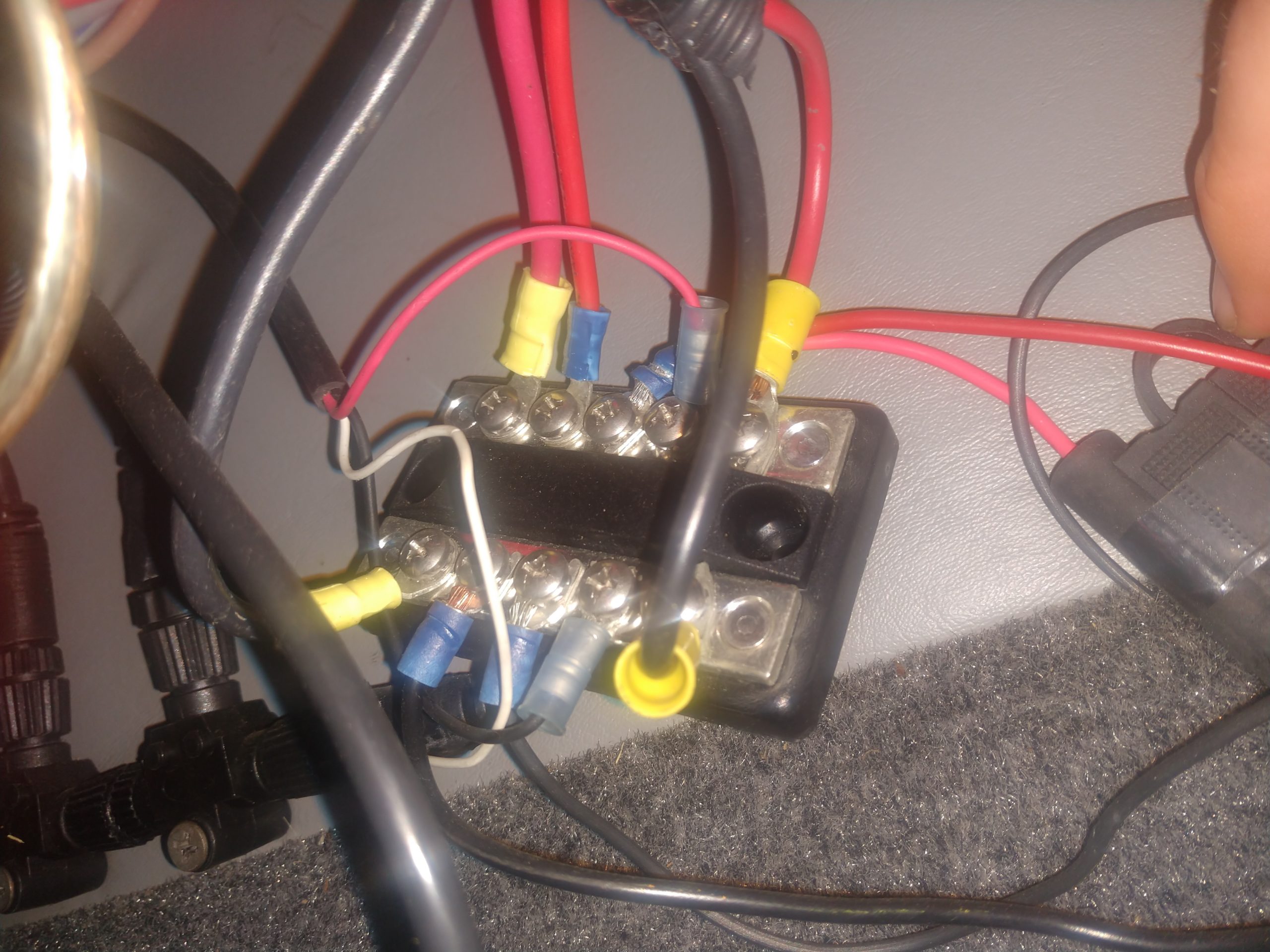
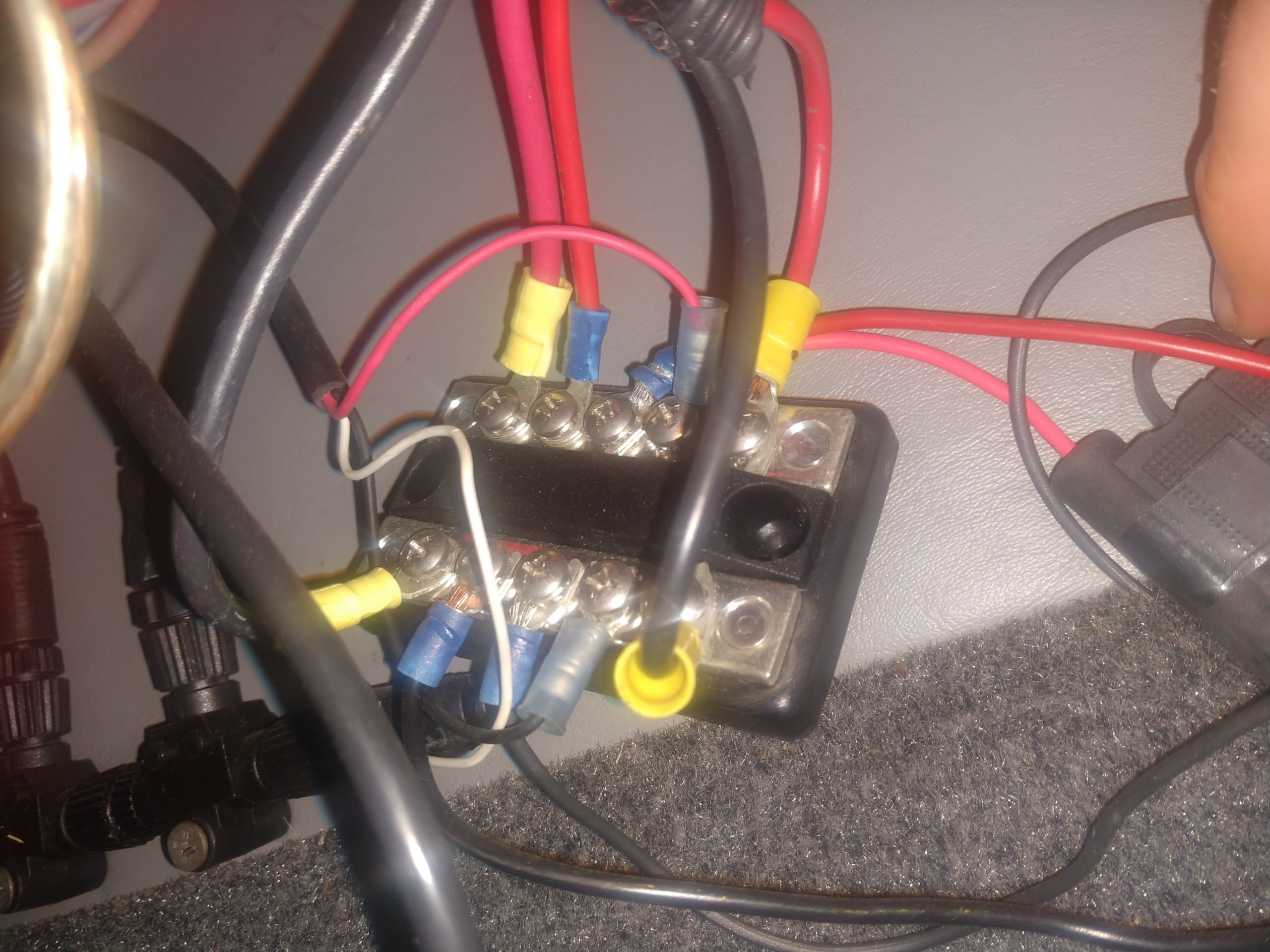
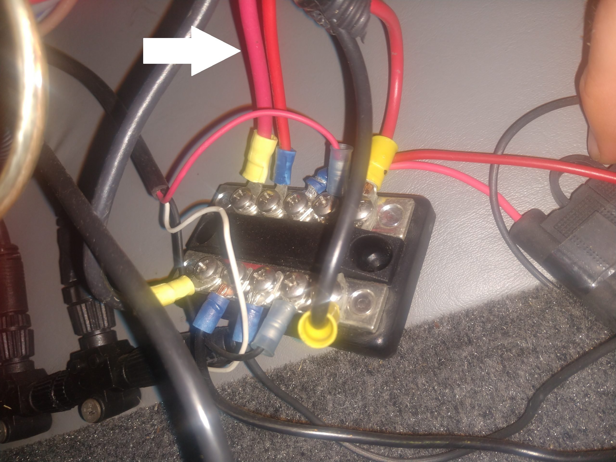
    My confusion set in when I look that my existing one has a larger gauge wire on each end whether it be positive or negative, but my new busbars only have 1 big terminal.
    Its harder than heck to see where these wires go, but I am assuming the larger gauge wires go to either the breaker circuit or the switches. I have a master switch that must be turned on for any of the electronics to work. The master switch has that same gauge wire on two of the connections.
    Do I connect BOTH of the heavier gauge wires to the 1 post on the new busbars and then all the smaller wires which would be for the GPS units, etc to the smaller screws?
    I thought I had this figured out last Fall, but just getting around to doing it now and all sorts of confused.
    Here are two pics for reference. Help PLEASE!!! LOL

    Attachments:
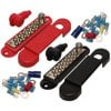
    1. 12terminalposnegbusbar-1.jpeg

    2. IMG_20210601_130826283-1-scaled.jpg

    3. 12terminalposnegbusbar.jpeg

    4. IMG_20210601_130826283-scaled.jpg

    Hot Runr Guy
    West Chicago, IL
    Posts: 1934
    #2040139

    Since nothing is labeled, you’ll need to determine which is the “feed” line, and which is feeding your switch panel and other things.

    I’d pull this one off, and if nothing else works, that’s the one that goes to the threaded stud.

    HRG

    Blue Sea make a nice unit, that has 1/4-20 studs at both ends, plus 5 screw terminals.

    https://www.bluesea.com/products/2722/DualBus_Plus_150A_BusBar_-_1_4in-20_Stud_5_Gang

    Attachments:
    1. IMG_20210601_130826283-scaled-1.jpg

    CaptainMusky
    Posts: 19401
    #2040142

    Thanks! I will give it a shot I could also use a voltmeter I suppose to just check which is incoming.
    It’s just the one big post on the new one that had me confused

    CaptainMusky
    Posts: 19401
    #2040154

    Well, I checked with the voltmeter and neither of those larger gauge wires have power unless I flip the master switch, then they have power. So my thought process is BOTH of those should probably go on the 1 larger terminal of my new busbar and then the rest will go on the screws.
    I too thought that one of them had to be power in, but that must go up to the dash then down to this mini busbar. I might just say eff it and leave it alone before I burn my boat and garage down. LOL

    Hot Runr Guy
    West Chicago, IL
    Posts: 1934
    #2040160

    Well, I checked with the voltmeter and neither of those larger gauge wires have power unless I flip the master switch, then they have power. So my thought process is BOTH of those should probably go on the 1 larger terminal of my new busbar and then the rest will go on the screws.
    I too thought that one of them had to be power in, but that must go up to the dash then down to this mini busbar. I might just say eff it and leave it alone before I burn my boat and garage down. LOL

    I’ve got to ask, did you dis-connect the (2) large wires from the busbar before you checked the voltage? If you left them connected, of course they will both still see voltage.

    HRG

    CaptainMusky
    Posts: 19401
    #2040164

    I’ve got to ask, did you dis-connect the (2) large wires from the busbar before you checked the voltage? If you left them connected, of course they will both still see voltage.

    HRG

    I left them both connected because I thought one of the two leads was incoming power right from the battery and then the other I was thinking fed the switch. Neither of them have power when the switch is off so that certainly means neither is the power in straight from the battery like I was thinking.

    Hot Runr Guy
    West Chicago, IL
    Posts: 1934
    #2040166

    <div class=”d4p-bbt-quote-title”>Hot Runr Guy wrote:</div>
    I’ve got to ask, did you dis-connect the (2) large wires from the busbar before you checked the voltage? If you left them connected, of course they will both still see voltage.

    HRG

    I left them both connected because I thought one of the two leads was incoming power right from the battery and then the other I was thinking fed the switch. Neither of them have power when the switch is off so that certainly means neither is the power in straight from the battery like I was thinking.

    10-4. So one is probably coming from the switch, the other is probably feeding the rest of the dash circuits. One side of the switch should have the main power feed from the battery.

    HRG

    CaptainMusky
    Posts: 19401
    #2040169

    10-4. So one is probably coming from the switch, the other is probably feeding the rest of the dash circuits. One side of the switch should have the main power feed from the battery.

    HRG

    I like the one you shared earlier. I probably should have gotten one like that instead. Its going to start getting hot outside now and I am not going to want to be laying in the boat in the garage so I am going to kick this down the road for later I think. Thanks for the help!

Viewing 8 posts - 1 through 8 (of 8 total)

You must be logged in to reply to this topic.