12 volt DC motor reversing schematic or description

  • The_Bladepuller
    South end
    Posts: 739
    #2034779

    I have a 12 volt DC permanent magnet winch motor on my boat hoist. The OEM plastic enclosure box for the controls fell apart. I have replaced relays that had gone bad in it before. I bought new weather tight box and new waterproof relays. The existing relays were still good but were not water proof so I went with the same spec of relay from the OEM, just a waterproof one. The local lift mfgr is not & did not previously furnish any support. They sell a solid state replacement for > $500. Being “old school” I trust mechanical relays vs microchips.
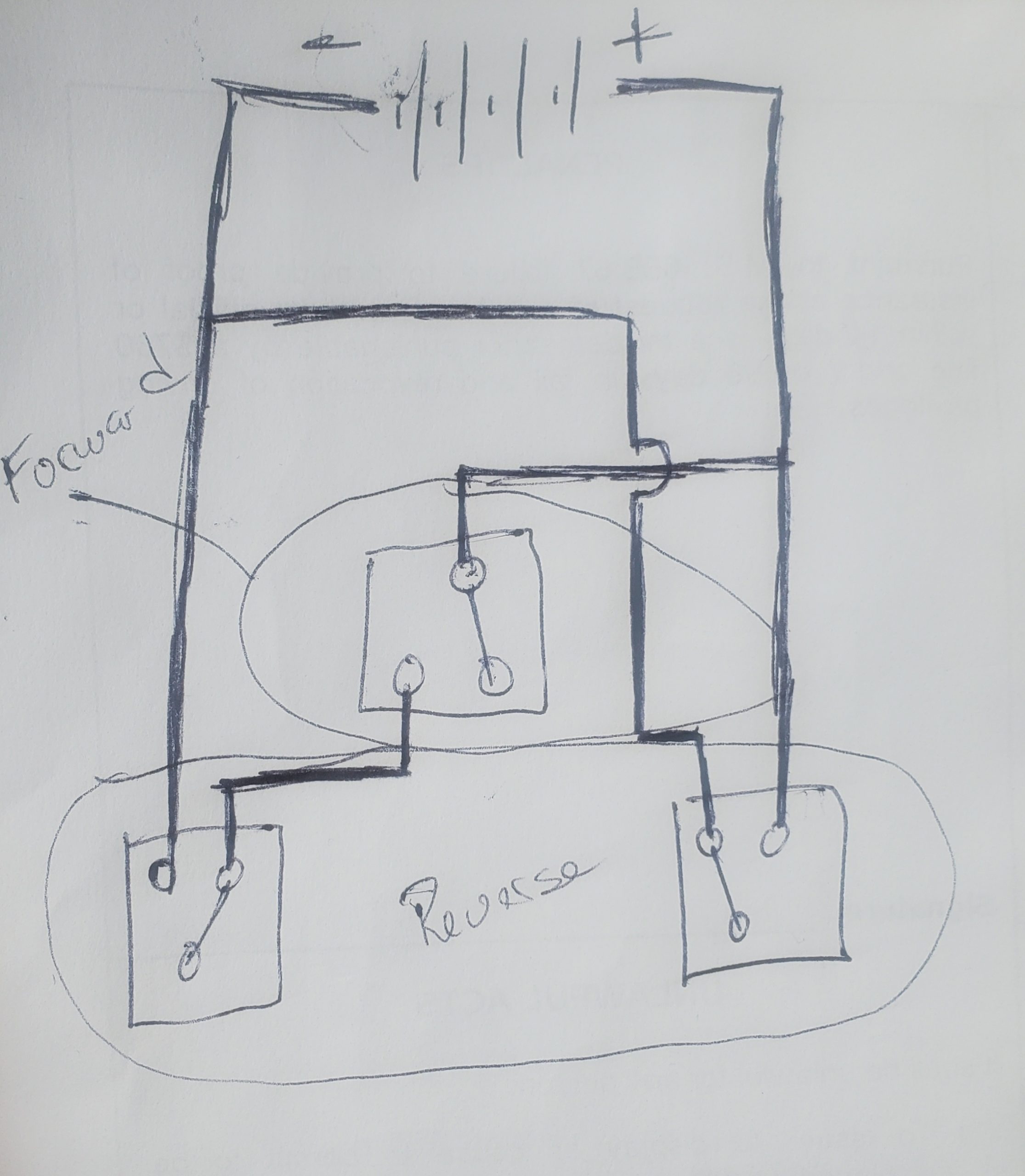
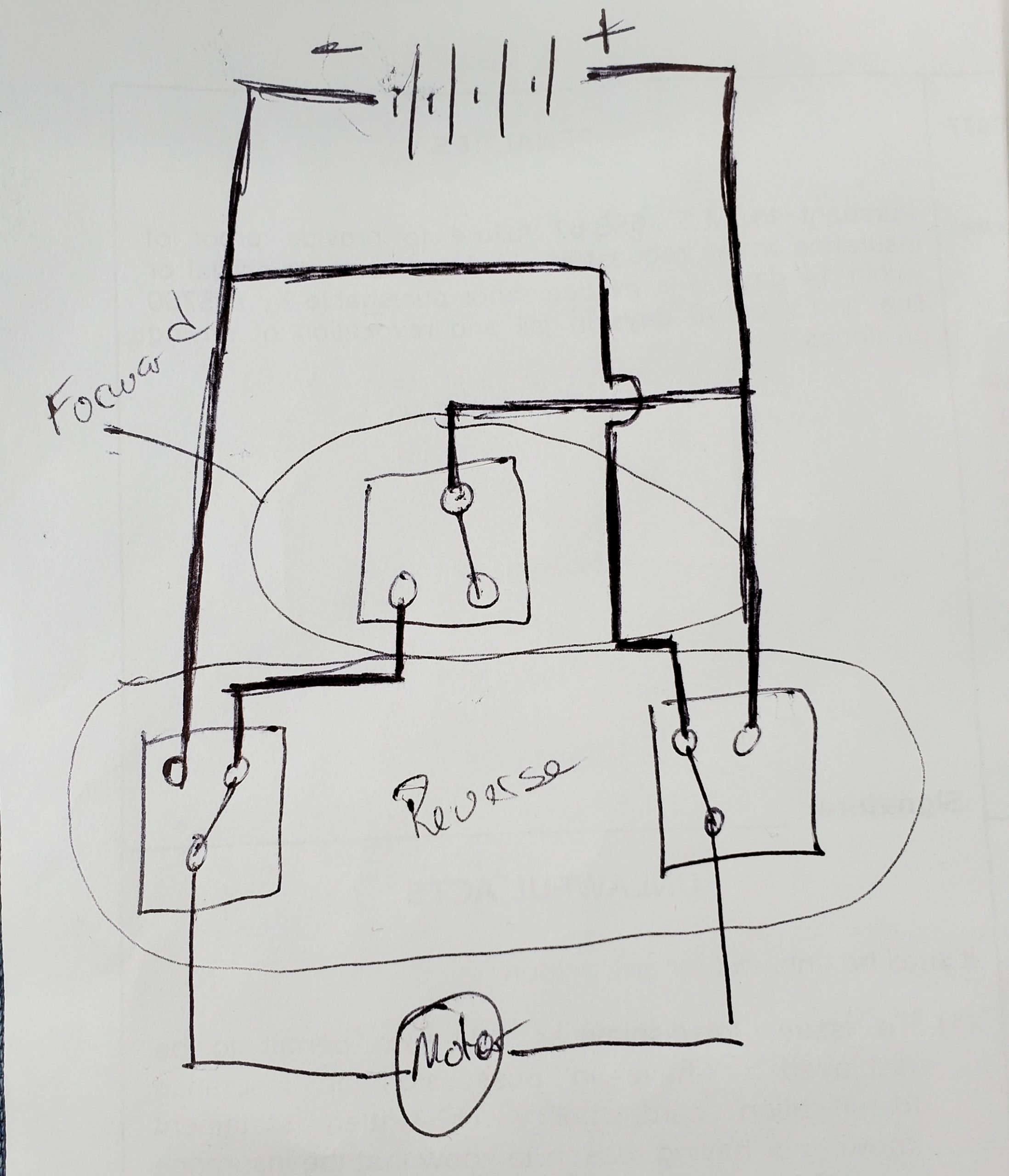
    I have not had the lift in use for a couple years but things are changed. I had some scribbled notes on the previously successful repair but can’t find it. Wondering if anyone here has used relays and a jumper wire to reverse DC. The parts are:
    12 V motor w/ a single + & – lead. Female connector
    12 V battery with a single + & 2 – on a common wire. Female connectors
    (3) identical relays with 3 large (heavy amps) blade connectors. There are 2 smaller control male connectors that control the relay solenoid on each relay.
    A 3 female blade connector jumper ( sized to handle amps) that “back feeds” + off the battery to the neg on the motor.
    A seperate 2 push button box uses a common ground & acts as a switch leg. Connects into small gauge control wiring. I have a handle on this.
    Limit switch that also is conrol wiring and will function to interupt relay solenoid
    If any one could give me some insight I’d appreciate it. How do you create a X of current with 3 relays and a 3 lug jumper wire?

    Jeff Gilberg
    Posts: 134
    #2034799

    On a permanent magnet brushed motor, all you need to do to reverse the motor is to reverse the polarity (+ -) to the motor.

    The_Bladepuller
    South end
    Posts: 739
    #2034825

    Jeff,
    I totally get that.
    See the verbiage about using relays and a jumper wire.

    Dave maze
    Isanti
    Posts: 912
    #2034837

    Does this help? You would still need to incorporate your limit switches and power for the coils of the relays.

    Attachments:
    1. reversible-dc-motor-using-2-relays.gif

    Jeff Gilberg
    Posts: 134
    #2034841

    can you show me the relays you plan on using ?

    munchy
    NULL
    Posts: 4666
    #2034870

    Separate the relays into two controlled circuits.

    The one relay will be for forward. The two relays will be for reverse.

    Attachments:
    1. 20210505_140115-scaled.jpg

    munchy
    NULL
    Posts: 4666
    #2034912

    Just realized I forgot to put the motor into the schematic.

    Attachments:
    1. 20210505_154335-scaled.jpg

    Jeremy
    Richland County, WI
    Posts: 687
    #2034938

    Just by a contactor/relay made for an ATV winch, use limit switches that are normally closed and run the control power through them before the contactor. It shouldn’t have to be much different compared to tilt/trim or an ATV control circuit other than the limit switches

Viewing 8 posts - 1 through 8 (of 8 total)

You must be logged in to reply to this topic.