Quote:
Thanks for the info. I guess I never thought of how the side imaging would work being clamped to the trolling motor.. Any bass guys have these and if so, how do you deal with the front. I understand what you guys that troll are saying. I fish bass so I stand on the trolling motor most of the time.
Bass guy??? I’ve caught a few of those green and golden carp – LOL
I have a 1197 ram mounted forward of my console. For two years I have rotated the gimbal so I can view the screen while up on the deck. What I don’t like about doing that is looking back at the screen while I’m usually facing quartered forward and the hassle of turning it every time I start / stop.
As stated above, go with a Interlink (runs about $125.00) and you can network the components together. That way your bow and console units see the exact same thing.
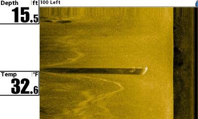
Kooty – yes, you want to be moving to see best quality SI images. I had Mike Watson out last year on pool 8 and we were looking at some big trees in the current of a fast moving slough while I was moving about .9 mph with the trolling motor. Not the best quality, but you could clearly see all the limbs and debri
Here is some interlink info
531567-1_D
InterLink™ Controller
531567-1_D – InterLink_Man.qxp 3/27/2007 3:57 PM Page 1
Thank You!
Thank you for choosing Humminbird®, America’s #1 name in fishfinders.
Humminbird® has built its reputation by designing and manufacturing topquality,
thoroughly reliable marine equipment. Your Humminbird® accessory is
designed for trouble-free use in even the harshest marine environment. In the
unlikely event that your Humminbird® accessory does require repairs, we offer
an exclusive Service Policy – free of charge during the first year after purchase,
and available at a reasonable rate after the one-year period. For complete
details, see the warranty included in this manual. We encourage you to read
this operations manual carefully in order to get full benefit from all the
features and applications of your Humminbird® product.
Contact our Customer Resource Center at either 1-800-633-1468 or visit our
website at http://www.humminbird.com.
WARNING! This device should not be used as a navigational aid to prevent
collision, grounding, boat damage, or personal injury. When the boat is moving,
water depth may change too quickly to allow time for you to react. Always operate
the boat at very slow speeds if you suspect shallow water or submerged objects.
WARNING! Disassembly and repair of this electronic unit should only be
performed by authorized service personnel. Any modification of the serial number
or attempt to repair the original equipment or accessories by unauthorized
individuals will void the warranty. Handling and/or opening this unit may result in
exposure to lead, in the form of solder.
WARNING! This product contains lead, a chemical known to the state of
California to cause cancer, birth defects and other reproductive harm.
NOTE: Your control head might require a software upgrade to be compatible with
the InterLink™ accessory. See http://www.humminbird.com for more information.
Humminbird®, InterLink™, HumminbirdPCTM, X-Press™ Menu, SmartCast® and WeatherSense® are
trademarked by or registered trademarks of Humminbird®.
© 2007 Humminbird®, Eufaula AL, USA. All rights reserved.
531567-1_D – InterLink_Man.qxp 3/27/2007 3:57 PM Page 2
How the InterLink™ Works 1
InterLink™ Installation Overview 3
InterLink™ Connection Kit 3
Connecting Your InterLink™ to the Control Head(s) 4
The Menu System 10
Start-Up Options Menu 13
Normal Operation 14
Simulator 14
System Status 15
Self Test 16
Accessory Test 17
GPS Diagnostic View 18
PC Connect (with PC Connect Cable only) 19
How the InterLink™ Affects the Control Head User Interface 20
Sharing Data ……………………………………………………………………………………………….. 22
Sharing Waypoints ………………………………………………………………………………………. 23
Sharing Routes ……………………………………………………………………………………………. 25
InterLink™ Submenu …………………………………………………………………………………… 27
Troubleshooting 29
Fishing System Doesn’t Power Up…………………………………………………………………. 29
Fishing System Defaults to Simulator with a Transducer Attached…………………… 29
Control Head Doesn’t Recognize InterLink™ when the InterLink™ is Attached …….. 30
Display Problems ………………………………………………………………………………………… 31
Finding the Cause of Noise ………………………………………………………………………….. 32
i
Table of Contents
531567-1_D – InterLink_Man.qxp 3/27/2007 3:57 PM Page i
ii
Table of Contents
Humminbird® Accessories 33
Maintenance 34
Humminbird® 1-Year Limited Warranty 34
Humminbird® Service Policy 35
Returning Your Unit For Service 36
In-Warranty Service …………………………………………………………………………………….. 36
Out-of-Warranty Service……………………………………………………………………………….. 36
Notes 37
Contact Humminbird® 38
NOTE: Entries in this Table of Contents which list (with PC Connect Cable only)
require the purchase of a separate accessory. You can visit our website at
http://www.humminbird.com to order these accessories online or contact our Customer
Resource Center at 1-800-633-1468.
531567-1_D – InterLink_Man.qxp 3/27/2007 3:57 PM Page ii
1
How the InterLink™ Works
Your InterLink™ Network Connection allows you to share accessory data, GPS
position, waypoints, routes and your current track between two Humminbird®
Fishing Systems in real time. When sharing is enabled, for example, you can
mark a waypoint using one Fishing System, and it becomes instantly available
on the second Fishing System. Also, some accessories, such as the
WeatherSense® Fishing Condition Monitor, can be shared and controlled from
both control heads.
NOTE: The InterLink™ does not support data sharing of sonar information, which
includes the Wireless Sonar Link (WSL) accessory and transducer data.
Your InterLink™ keeps a collection of shared objects and the sequence number
of each change made to that collection. When you make a change to navigation
data, the InterLink™ compares the changes with the existing data and updates
it appropriately.
The InterLink™ can hold up to 3,000 saved shared waypoints, 50 saved shared
routes of 50 saved waypoints each, the current route, the current route’s
waypoints, and the current track. The number of waypoints and routes that
can be shared using the InterLink™ is limited by the capacity of the smaller of
the two networked control heads. For example, if a unit with a 3,000 waypoint
capacity and 1,000 locked waypoints is networked with a 750 waypoint
capacity unit holding 200 locked waypoints, the number of shared waypoints
will be restricted to a maximum of 550 waypoints. This is the remaining
capacity of the smaller unit (3,000 – 1,000=2000> 750 – 200 = 550).
Waypoints and routes are shared as follows:
• When a shared waypoint is added on a control head, it is added to the
InterLink™, and also to the other control head, if it is connected to the
InterLink™ and powered up.
• When a shared waypoint is edited on a control head, it is modified on
the InterLink™, as well as on the other control head.
531567-1_D – InterLink_Man.qxp 3/27/2007 3:57 PM Page 1
• When a shared waypoint is deleted from a control head, it is deleted
on the InterLink™, and also from the other control head.
• When you request to share a non-shared waypoint from one control
head, it is added to the InterLink™, and also to the other control head
(as long as the capacity of the smaller of the two control heads will
allow it).
• When you request to stop sharing a shared waypoint on one control
head, it is deleted from the InterLink™, and also from the other
control head.
• When you add a shared route, edit a shared route, or make a nonshared
route shared, all affected waypoints are also automatically
shared. If the capacity of any of the units cannot handle the additional
waypoints, this operation may not succeed.
• When you change the status of a shared route to non-shared, or
remove a waypoint from a shared route, the affected waypoints remain
shared, since they may be used in other shared routes.
You can also daisy chain InterLink™ with other Humminbird® accessories such
as a WeatherSense® in order to create a network that lets you share digital
data around the boat. GPS and accessory data sharing begins as soon as the
InterLink™ is connected, and is always functioning.
NOTE: Functionality may be limited based on the model you are using.
Chartplotters and units that are not combo units may be limited in the types of data
that they can send and recieve.
NOTE: To avoid any data corruption or loss, Humminbird® recommends that you
backup all waypoints and routes via an MMC/SD card or through Humminbird® PC
before sharing, editing, and deleting data across the InterLink™.
2
531567-1_D – InterLink_Man.qxp 3/27/2007 3:57 PM Page 2
InterLink™ Installation Overview
You will need to connect your InterLink™ to your two Humminbird® Fishing
System control heads. The location of the InterLink™ and the accessory daisy
chain is critical to ensure proper operation; please read all installation
instructions carefully before installing.
NOTE: The InterLink™ will only support 2 Humminbird® Fishing System control
heads at a time.
InterLink™ Connection Kit
The Humminbird® InterLink™ Controller Connection Kit includes the
following items:
• InterLink™
• One 10-foot cable for attaching the first control head
• One 20-foot cable for attaching the second control head
• Hardware kit for stand-alone or stack mounting
• InterLink™ Accessory Manual.
NOTE: 10 foot extension cables are available as optional-purchase items. These
can be used to extend the total cable length up to 50 feet.
3
531567-1_D – InterLink_Man.qxp 3/27/2007 3:57 PM Page 3
Connecting Your InterLink™ to the Control Head(s)
Perform the following procedure to connect your InterLink™ to your
Humminbird® Fishing System control heads.
Perform the following installation procedure for your InterLink™ Accessory:
1. Lay out the cables and the InterLink™ to make sure that the cables
will reach both control heads.
2. Interconnect the “To Control Head 1” connector either directly to the
COM port on the control head or to the “Daisy Chain” connector of an
accessory which is already attached to the control head. See the
Accessory System Interconnects diagrams for more information.
NOTE: Several installation scenarios are depicted in the Accessory System
Interconnects graphics on the following pages. Pick the one which best represents
your configuration on your boat. The GPS receiver can be connected directly to the
Interlink™ as shown in Scenario 2, or directly to the control heads as shown in
Scenarios 1 and 3.
CAUTION: It is very important to install the Interlink™ at the end of the daisy chain
of any accessories attached to either control head for data sharing to occur correctly.
InterLink™ Ports
1 2 GPS
To GPS Receiver
To Control Head 2
To Control Head 1
4
531567-1_D – InterLink_Man.qxp 3/27/2007 3:57 PM Page 4
NOTE: 10’ extension cables may be purchased from Humminbird® if your planned
cable route exceeds 20’ (6 m). Maximum cable length, including extension cables,
should not exceed 50’ (16 m). Visit our website at http://www.humminbird.com, or call
our Customer Resource Center at 1-800-633-1468 to purchase extension cables.
3. Connect the “To Control Head 2” connector either directly to the COM
port on the control head or to the daisy chain connector of an
accessory already attached to the control head. See the Accessory
System Interconnects diagram for more information.
NMEA-COM
ACCY-COM
COM
ACCY-COM ACCY-COM ACCY-COM
WeatherSense®
Smartcast™WSL
AS-YC (“Y”) Cable
GPS Receiver
Accessory
Fishing System
=
=
=
COM
Fishing System
COM
GPS Data
Accessory Data
Navigation Data
Navigation Data
Accessory
InterLink™
Accessory System Interconnects, Scenario 1
5
531567-1_D – InterLink_Man.qxp 3/27/2007 3:57 PM Page 5
ACCY-COM
Fishing System
COM
Fishing System
COM
GPS Data
GPS Data
Accessory Data
Accessory Data
Navigation Data
Navigation Data
ACCY-COM ACCY-COM ACCY-COM
WeatherSense®
Smartcast™WSL
GPS Receiver
Accessory
=
=
=
Accessory
InterLink™
Accessory System Interconnects, Scenario 2
6
531567-1_D – InterLink_Man.qxp 3/27/2007 3:57 PM Page 6
ACCY-COM
Fishing System
COM
Fishing System
COM
GPS Data
Accessory Data
Navigation Data
Navigation Data
NMEA-COM
ACCY-COM
COM
ACCY-COM ACCY-COM
WeatherSense®
Smartcast™WSL
AS-YC (“Y”) Cable
GPS Receiver
Accessory
Accessory
InterLink™
Accessory System Interconnects, Scenario 3
7
531567-1_D – InterLink_Man.qxp 3/27/2007 3:57 PM Page 7
NOTE: If more than one GPS receiver is installed on the boat, the control heads
interpreting the data from these GPS receivers may display slightly different
locations due to the nature of GPS calculations.
4a. If the InterLink™ will stand alone on the mounting surface, use the
four included M3x12 thread-forming screws to connect the two plastic
feet to the bottom of the InterLink™, two screws for each foot.
Preparing the InterLink™ for Stand-Alone Mounting
or…
4b. If you will be stacking the InterLink™ with another compatible
Humminbird® accessory, use two of the included M3x12 threadforming
screws to connect the two accessories, stacked one on top of
the other. Proceed to Step 6.
Install the Plastic Feet
Plastic Foot
M3x12
Screws
8
531567-1_D – InterLink_Man.qxp 3/27/2007 3:57 PM Page 8
Preparing the InterLink™ for Stack Mounting
5. Use the installed plastic feet to mark and then drill the two 1/8” holes to
a depth of 5/8″ in the mounting surface, one for each foot, needed to
attach the InterLink™ to the boat. Fill the holes in the mounting surface
with marine-grade silicone sealant, then attach the InterLink™ to the
mounting surface using the two included #8 x 5/8″ wood screws.
NOTE: On fiberglass hulls, it is best to use progressively larger drill bits to reduce
the chance of chipping or flaking the outer coating.
NOTE: Apply marine-grade silicone caulk or sealant to both screw and drilled holes
as needed to protect your boat from water damage.
NOTE: If the mounting surface is thin or made of a light-weight material, you may
need to add reinforcing material below the mounting surface in order to support
the InterLink™.
6. When the control head detects the InterLink™, the InterLink™ menu
items will be added automatically to the Menu system. This includes
an InterLink™ Setup Dialog Box which appears when you power up
either control head. See How the InterLink™ Affects the Control
Head User Interface for more information.
Stack Mounting Two Units
M3x12
Screw
M3x12
Screw
9
531567-1_D – InterLink_Man.qxp 3/27/2007 3:57 PM Page 9
The Menu System
The menu system is divided into easy-to-use menu modules. The main
components of the menu system are:
Start-Up Options Menu – Press the MENU key during the power up sequence
to view the Start-Up Options menu.
X-Press™ Menu – The X-Press™ menu allows
you to access the settings that are changed
frequently without having to navigate through
the whole menu system. Press the MENU key
once to display the X-Press™ Menu. When you
select a menu item from the X-Press™ menu,
the menu will collapse, leaving only the menu
choice on the screen. Use the UP or DOWN
Cursor keys to reactivate the X-Press™ menu.
NOTE: The X-Press™ Menu choices will vary
depending on which view is active when you
press the MENU key, as well as whether you are
in Normal or Advanced User Mode.
X-PressTM Menu
10
531567-1_D – InterLink_Man.qxp 3/27/2007 3:58 PM Page 10
11
Main Menu Tabs – Less frequently-adjusted
menus are grouped into the Main Menu
System. The Main Menu system is organized
under tab headings to help you find a specific
menu item quickly.
Press the MENU key twice for the Main Menu,
then use the 4-WAY Cursor LEFT or RIGHT key
to select a tab, and use the DOWN or UP key
to select a specific menu item under that tab,
then use the LEFT or RIGHT keys again to
change a menu setting. Press the EXIT key to
move quickly to the top of the tab. A down
arrow at the bottom of a menu means that you
can scroll to additional menu choices using
the DOWN Cursor key. A right or left arrow on
a menu choice means that you can use the
RIGHT or LEFT Cursor keys to make changes or
to see more information.
NOTE: The Main Menu choices will vary depending on whether you are in Normal
or Advanced User Mode.
User Mode (Normal or Advanced) – An Advanced Mode is provided for users
who desire the highest level of control over the Fishing System and Normal
Mode for users who desire greater simplicity and fewer menu choices.
Additional Advanced menu choices will be displayed throughout the menu
system when you navigate to specific menus while in Advanced Mode. Any
changes made while in Advanced Mode will remain in effect after you switch
back to Normal Mode. For example, if you set specific views to be visible while
in Advanced User Mode, and then return to Normal User Mode, those views
will still be visible.
Main Menu System
Normal User Mode
531567-1_D – InterLink_Man.qxp 3/27/2007 3:58 PM Page 11
Total Screen Update – when you change any menu settings that affect the
current view, the view will update immediately (i.e. you don’t have to exit the
menu to apply the change to the screen).
Setup Tab,
Normal Mode Setup Tab,
Advanced Mode
12
531567-1_D – InterLink_Man.qxp 3/27/2007 3:58 PM Page 12
Start-Up Options Menu
Press the MENU key when the Title screen is displayed to access the Start-Up
Options menu.
Use the UP or DOWN 4-WAY Cursor keys to position the cursor, then the RIGHT
Cursor key to select one of the following choices. If you wait too long, the
system will default to whichever menu mode happens to be highlighted:
• Normal
• Simulator
• System Status
• PC Connect (use with PC Connect Cable).
See the following paragraphs for more information about each of these choices.
Start-Up Options Menu
13
531567-1_D – InterLink_Man.qxp 3/27/2007 3:58 PM Page 13
Normal Operation
Use Normal operation for on the water operation with a transducer
connected. In addition, your Fishing System uses advanced transducer
detection methods to determine if a transducer is connected. If a functioning
transducer is connected, Normal operation will be selected automatically at
power up and your Fishing System can be used on the water.
Exit Normal operation by powering your Fishing System off.
Simulator
Use the Simulator to learn how to use your Fishing System before taking your
boat on the water. The Simulator is a very powerful tool that simulates on the
water operation, providing a randomly-updated display. We recommend going
through this manual while using the Simulator, since all of the menus function
and affect the display the way they actually do when in Normal operation.
Simulator, Shown with optional
Speed/Temp and WeatherSense® Accessories
14
531567-1_D – InterLink_Man.qxp 3/27/2007 3:58 PM Page 14
NOTE: To get the full benefit of the Simulator, it is important to select Simulator
manually from the Start-Up Options menu as opposed to letting the Fishing System
enter Simulator automatically (as it will if a transducer is not connected and you do
nothing during power up). Manually selecting Simulator from the Start-Up Options
menu allows you to pre-configure your Fishing System for on the water operation.
Any menu changes you make will be saved for later use.
A message will appear on the display periodically to remind you that you are
using the Simulator.
Exit the Simulator by powering your Fishing System off.
System Status
Use System Status to view system connections and to conduct a unit self-test.
The following screens are displayed in turn when you press the VIEW button
when using System Status:
• Self Test
• Accessory Test
• GPS Diagnostic View.
• PC Connect (with optional-purchase PC Connect Cable only).
Exit System Status by powering your Fishing System off.
15
531567-1_D – InterLink_Man.qxp 3/27/2007 3:58 PM Page 15
Self Test
Self Test displays results from the internal diagnostic self test, including unit
serial number, Printed Circuit Board (PCB) serial number, software revision,
total hours of operation and the input voltage.
System Status Self Test Screen
16
531567-1_D – InterLink_Man.qxp 3/27/2007 3:58 PM Page 16
Accessory Test
Accessory Test lists the accessories connected to the system.
NOTE: The speed accessory will be detected only if the paddlewheel has moved
since your Fishing System was powered up.
NOTE: GPS will be shown as Connected when your Fishing System detects a GPS
Receiver.
NOTE: InterLink™ will be shown as Connected when your Fishing system detects
an InterLink™.
Accessory Test Screen
17
531567-1_D – InterLink_Man.qxp 3/27/2007 3:58 PM Page 17
GPS Diagnostic View
GPS Diagnostic View shows a sky chart and numerical data from the GPS
receiver. The sky chart shows the location of each visible GPS satellite with its
satellite number and a signal strength bar. A dark gray bar indicates that the
satellite is being used to determine your current position. A light gray bar
indicates that the satellite is being monitored, but is not yet being used.
NOTE: The GPS Diagnostic View only appears if the GPS Receiver is connected.
This view also reports the current position, local time and date, and other
numeric information. The current GPS Fix Type is reported as No Fix, 2D Fix, 3D
Fix, or Enhanced. An Enhanced fix has been augmented using information
from WAAS, EGNOS, or MSAS. A 3D or Enhanced Fix is required for navigation.
HDOP (the Horizontal Dilution of Precision) is a GPS system parameter which
depends on the current satellite configuration. HDOP is used to calculate the
Estimated Position Error.
GPS Diagnostic View
Satellite Being
Monitored
Satellite
Being Used
Current Latitude
and Longitude
Sky Chart
GPS Data Source
18
531567-1_D – InterLink_Man.qxp 3/27/2007 3:58 PM Page 18
PC Connect (With PC Connect Cable only)
Use PC Connect to update the software of the Fishing System control head.
This feature requires the use of the PC Connect Cable. Complete instructions
are included with the PC Connect Cable accessory.
NOTE: The PC Connect Cable requires a separate purchase. For more information
visit our website at http://www.humminbird.com or contact our Customer Resource
Center at 1-800-633-1468.
Exit PC Connect mode by powering the Fishing System off.
NOTE: Your control head might require a software upgrade to be compatible with
the InterLink™ accessory. See http://www.humminbird.com for more information.
19
531567-1_D – InterLink_Man.qxp 3/27/2007 3:58 PM Page 19
How the InterLink™ Affects the Control Head User Interface
The first time a control head is connected, it sends its serial number to the
InterLink™, and several scenarios are possible:
• If the InterLink™ recognizes the control head as a participant, data
synchronization occurs. If data has changed outside of the network,
the InterLink™ may ask which data to synchronize.
• If the InterLink™ does not recognize the control head as a participant,
registration begins. First, the InterLink™ sends its status (number of
shared waypoints and routes stored, as well as its current capacity) to
the control head to determine which of the four options is available.
Then, you will be given a choice of the available options via the
InterLink™ Setup dialog box which appears when you power up either
control head.
InterLink™ Setup Dialog Box
20
531567-1_D – InterLink_Man.qxp 3/27/2007 3:58 PM Page 20
The options are:
1. Ignore the InterLink™ network – This option is always available.
Choosing this options means that the InterLink™ will be ignored
until this option is changed using the InterLink™ submenu on the
Accessory main menu tab.
2. Send shared data to the InterLink™ – This one-time option is available
only if the data on the control head can fit on the InterLink™. This may
require that all duplicate data on the InterLink™ is downloaded to the
control head, so that only non-duplicate data is stored on the
InterLink™ to save space. After this operation is complete, the control
head will ignore the InterLink™ until the next time it is powered off
and on again.
3. Receive shared data from the InterLink™ – This one-time option is
available only if the data in the InterLink™ can fit onto the control
head. After this operation is complete, the control head ignores the
InterLink™ until the next time it is powered off and on again.
4. Fully participate in the network – This option is available if the data in
the InterLink™ fits onto the control head and the data in the control
head fits onto the InterLink™. When you select this option, data in the
InterLink™ and shared data on the control head are merged, and
kept synchronized, so that changes to one will change the other.
The InterLink™ stores the serial numbers, data capacities, and the
sequence number of the last synchronization for both control heads.
NOTE: Participation can be changed at any time using the InterLink™ submenu on
the Accessory main menu tab.
21
531567-1_D – InterLink_Man.qxp 3/27/2007 3:58 PM Page 21
Sharing Data
If there is room on the network, all waypoints and routes will be
automatically shared.
The following rules apply to navigation data sharing:
• Saved waypoints and routes are shareable.
• If a route is being shared, all the waypoints contained in that route are
also shared.
• The current route is shared by both control heads, but navigation
parameters are computed by each control head separately. Waypoints
in the current route are temporarily shared.
• Saved tracks are not shared.
• Data sharing will not affect sonar performance.
To find out what data is being shared, use the Accessories main menu tab to
select the InterLink™ menu. See InterLink Status for more information.
22
531567-1_D – InterLink_Man.qxp 3/27/2007 3:58 PM Page 22
Sharing Waypoints
You can determine which waypoints to lock or to share by selecting the Share
option from the Waypoints submenu under the Navigation main menu tab.
Choosing Share displays the Select Waypoints to Share dialog box. See the
Select Waypoints to Share Dialog Box illustration for more information.
Select Waypoints to Share Dialog Box
Waypoints Submenu
23
531567-1_D – InterLink_Man.qxp 3/27/2007 3:58 PM Page 23
From the Select Waypoints to Share box, you can choose to share all of the
waypoints, lock all of the waypoints, or mark the waypoints individually. Once
you mark the waypoints that you want to share, press the EXIT key and a
message will come up asking you to confirm your changes. If at any point you
select too much data to send to the InterLink™, an error message will appear
that tells you how many excess waypoints you have selected. Press the EXIT
key to adjust your selection to fit the capacity available. Changes will not be
saved until the number of shared waypoints is within the allowable limit.
Excess Data Error Message
24
531567-1_D – InterLink_Man.qxp 3/27/2007 3:58 PM Page 24
Sharing Routes
You can determine which routes to lock or to share by selecting the Share
option from the Routes submenu under the Navigation main menu tab.
Choosing Share displays the Select Routes to Share dialog box. See the Select
Routes to Share Dialog Box illustration for more information.
Select Routes to Share Dialog Box
Routes Submenu
25
531567-1_D – InterLink_Man.qxp 3/27/2007 3:58 PM Page 25
26
From the Select Routes to Share box, you can choose to share all of the routes,
lock all of the routes, or mark the routes individually. Once you mark the routes
that you want to share, press the EXIT key and a message will come up asking
you to confirm your changes. If at any point you select too much data to send
to the InterLink™, an error message will appear that tells you how many
excess routes you have selected. If you have selected a route that causes too
many waypoints to be shared, a similar error message will also be displayed.
Press the EXIT key to adjust your selection to fit the capacity available.
Changes will not be saved until the number of shared routes is within the
allowable limit.
NOTE: Any of the routes you share will automatically cause the waypoints
contained in them to be shared as well.
531567-1_D – InterLink_Man.qxp 3/27/2007 3:58 PM Page 26
InterLink™ Submenu
To view the InterLink™ Submenu:
1. From the Accessories main menu, use the 4-WAY Cursor Control keys
to select InterLink.
2. Use the 4-WAY Cursor Control keys to choose options in the
InterLink™ submenu.
InterLink™ Status Window
Number of Routes the
InterLink™ Can Accept
Not Participating Icon
Number of Waypoints
the 755c Control Head
has Marked as Shared
Number of Waypoints
the 755c Control Head
has Marked as Locked
InterLink™ Submenu
27
531567-1_D – InterLink_Man.qxp 3/27/2007 3:58 PM Page 27
The InterLink™ Submenu contains the following menu choices:
InterLink™ Status allows you to see a listing of the data on the local control
head (the one you’re using), the remote control head (the other control head
attached to the InterLink™), and the InterLink™ itself. The InterLink™ status
window shows how much space is remaining on the Interlink™, how much
data is being shared across the Interlink, if a control head is participating,
how much data each control head is sharing, and how much data each
control head has locked.
Start Participating allows you to re-start the registration process for a control
head that is not currently participating.
Stop Participating allows you to un-register your control head from the
InterLink™.
28
531567-1_D – InterLink_Man.qxp 3/27/2007 3:58 PM Page 28
29
Troubleshooting
Before contacting the Humminbird® Customer Resource Center, please read
the following section. Taking the time to review these troubleshooting
guidelines may allow you to solve a performance problem yourself, and
therefore avoid sending your unit back for repair.
Fishing System Doesn’t Power Up
If your Fishing System doesn’t power up, use the Installation Guide that also
comes with it for specific confirmation details, making sure that:
• the power cable is properly connected to the Fishing System control head,
• the power cable is wired correctly, with red to positive battery terminal
and black to negative terminal or ground
• the fuse is operational
• the battery voltage of the power connector is at least 10 Volts.
Correct any known problems, including removing corrosion from the battery
terminals or wiring, or actually replacing the battery if necessary.
Fishing System Defaults to Simulator with a Transducer Attached
A connected and functioning transducer will cause the newly-started Fishing
System to go into Normal operating mode automatically. If, when you power
up the Fishing System, it goes into Simulator mode automatically, even though
a transducer is already connected, this means that the control head is not
detecting the transducer. Perform the following troubleshooting tasks:
• Using the Installation Guide that also comes with your Fishing System,
check to make sure that the transducer cable is securely connected to
the Fishing System. Reconnect if necessary, and power up the Fishing
System again to see if this fixes the problem.
531567-1_D – InterLink_Man.qxp 3/27/2007 3:58 PM Page 29
• Replace the non-functioning transducer with a known good transducer
if available and power up the control head again.
• Check the transducer cable. Replace the transducer if the cable is
damaged or corroded.
Control Head Doesn’t Recognize the InterLink™
when the InterLink™ is Attached
• If the InterLink™ is connected, but it isn’t being recognized, check the
Accessory Test View to make sure the InterLink™ is listed. If the
InterLink™ is not listed in the Accessory Test View, or if it is listed, but
it is not shown as Active, make sure that all of the interconnecting
cables are installed correctly.
NOTE: Your control head may require a software upgrade to be compatible with
InterLink™ accessory. See http://www.humminbird.com for more information.
30
531567-1_D – InterLink_Man.qxp 3/27/2007 3:58 PM Page 30
Display Problems
There are several main conditions or sources of possible interference that may
cause problems with the quality of the information displayed on the control
head. Look in the following table for some symptoms of display problems and
possible solutions:
Problem Possible Cause
The control head
loses power at
high speeds.
When the boat
moves at higher
speeds, the bottom
disappears or
suddenly weakens,
or the display
contains gaps.
There are no fish
detected, even
when you know
they are in the
water under the
boat, or sonar
readings seem
weak or faulty.
If the power output of your boat’s engine is unregulated, the control
head may be protecting itself using its over-voltage protection
feature. Make sure the input voltage does not exceed 20 Volts.
The transducer position may need to be adjusted. A mix of air and
water flowing around the transducer (cavitation) may be interfering
with the inter-pretation of sonar data. See your Installation Guide for
suggestions on adjusting the transducer position.
Electrical noise from the boat’s engine may be interfering with sonar
reception. See Finding the Cause of Noise for more information.
Sonar readings may be affected if the transducer is not positioned
correctly (i.e. mounted at an angle, not straight down), or there is
some kind of mechanical interference, either because it is
mounted inside a hull that is too thick for proper sonar
transmission, the bond between the transducer and the hull is not
airtight, or because the transducer is dirty. Check with your
Installation Guide for guidance on re-positioning the transducer,
and make sure the transducer is clean.
Low battery voltage may be affecting the power of signal
transmission.
Electrical noise from the boat’s engine may be interfering with sonar
reception. See Finding the Cause of Noise for more information.
31
531567-1_D – InterLink_Man.qxp 3/27/2007 3:58 PM Page 31
Finding the Cause of Noise
Electrical noise usually affects the display with many black dots at high
speeds, and high sensitivity readings. One or more of the following sources
can cause noise or interference:
Possible Source of Noise Isolation
Other electronic devices
The boat’s engine
Cavitation from the boat’s
propeller
Turn off any nearby electronic devices to see if
the problem goes away, then turn them on one
at a time to see if the noise re-appears.
To determine whether the boat’s engine is the
source of the noise, increase the RPMs while
the boat is in neutral and stationary to see if
the noise increases pro-portionately; if noise
appears when you rev the engine, the problem
could be the spark plugs, alternator, or
tachometer wiring. Replace the spark plugs
with resistor plugs, install an alternator filter, or
route the control head power and transducer
cables away from the engine wiring.
Turbulence created by the propeller can cause
noise; make sure the transducer is mounted at
least 15” (38 cm) from the propeller, and that
the water flows smoothly over the face of the
transducer at all times.
32
531567-1_D – InterLink_Man.qxp 3/27/2007 3:58 PM Page 32
33
Humminbird® Accessories
Accessories customize your Fishing System to your needs and enable you to stay
on the edge of new technology. When an accessory is connected to the Fishing
System, additional menus and readouts are added automatically to the Main
Menu System. Accessories available today that are supported by your Fishing
System include:
WeatherSense® Fishing Condition Monitor: purchase and plug in the
WeatherSense® accessory to your Fishing System to obtain barometric pressure
readouts and trend data in real time.
Wireless Sonar Link (WSL): purchase the Wireless Sonar Link (WSL) accessory to
receive remote sonar signals from a SmartCast® Remote Sonar Sensor (RSS). Radio
signals from the RSS are received by the WSL and are transmitted over the
Accessory Bus to the Fishing System.
PC Connect Cable: Purchase the PC Connect Cable to connect the Fishing System
to a PC in order to upload product software updates and new features obtained
from http://www.humminbird.com. This accessory requires the MSWindows-compatible
HumminbirdPC™ software downloaded from our website to your PC in order to
communicate with the Fishing System.
Be sure to check out our website http://www.humminbird.com for additional new and
exciting accessories to grow your Fishing System!
NOTE: Each accessory requires a separate purchase. You can visit our website
at http://www.humminbird.com or contact our Customer Resource Center at
1-800-633-1468 for additional details.
531567-1_D – InterLink_Man.qxp 3/27/2007 3:58 PM Page 33
Maintenance
If your boat remains in the water for long periods of time, algae and other marine
growth can reduce the effectiveness of the transducer. Periodically clean the face
of the transducer with hot water.
If your boat remains out of the water for a long period of time, it may take some
time to wet the transducer after it is returned to the water. Small air bubbles can
cling to the surface of the transducer and interfere with proper operation. These
bubbles will dissipate with time, or you may wipe the face of the transducer with
your fingers after the transducer is in the water.
1-Year Limited Warranty
We warrant the original retail purchaser that products made by Humminbird® have
been manufactured free from defects in materials and workmanship. This warranty
is effective for one year from the date of original retail purchase. Humminbird®
products found to be defective and covered by this warranty will be replaced or
repaired free of charge at Humminbird® option and returned to the customer
freight prepaid. Humminbird® sole responsibility under this warranty is limited to
the repair or replacement of a product that has been deemed defective by
Humminbird®. Humminbird® is not responsible for charges connected with the
removal of such product or reinstallation of replaced or repaired parts.
This warranty does not apply to a product that has been:
• Improperly installed;
• Used in an installation other than that recommended in the product
installation and operation instructions;
• Damaged or has failed because of an accident or abnormal operation;
• Repaired or modified by entities other than Humminbird®.
Please retain your original receipt as a proof of the purchase date. This will be
required for in-warranty service.
34
531567-1_D – InterLink_Man.qxp 3/27/2007 3:58 PM Page 34
THIS WARRANTY IS EXPRESSLY IN LIEU OF ANY OTHER WARRANTIES, OBLIGATIONS
OR LIABILITIES ON THE PART OF HUMMINBIRD® AND WILL BE THE CUSTOMER’S
EXCLUSIVE REMEDY, EXCEPT FOR ANY APPLICABLE IMPLIED WARRANTIES UNDER
STATE LAW WHICH ARE HEREBY LIMITED IN DURATION TO ONE YEAR FROM THE
DATE OF ORIGINAL PURCHASE. IN NO EVENT WILL HUMMINBIRD® BE LIABLE FOR
ANY INCIDENTAL OR CONSEQUENTIAL DAMAGES FOR BREACH OF ANY EXPRESS OR
IMPLIED WARRANTY RELATING TO THE PRODUCTS.
Some states do not allow limitations on an implied warranty, or the exclusion of
incidental or consequential damages, so the above exclusions may not apply to you.
You may also have other rights, which vary from state to state.
Humminbird® Service Policy
Even though you’ll probably never need to take advantage of our incredible service
policy, it’s good to know that we back our products this confidently. We do it because
you deserve the best. We will make every effort to repair your unit within three business
days from the receipt of your unit at our factory. This does not include shipping time to
and from our factory. Units received on Friday are typically shipped by the following
Wednesday, units received Monday are typically shipped by Thursday, etc.
All repair work is performed by factory-trained technicians to meet exacting factory
specifications. Factory-serviced units go through the same rigorous testing and
quality control inspections as new production units.
After the original warranty period, a standard flat rate service charge will be
assessed for each repair (physical damage and missing parts are not included).
Any repairs made after the original warranty will be warranted for an additional 90
days after service has been performed by our factory technicians. You can contact
our Customer Resource Center or visit our website to verify the flat rate repair fee
for your product (visit the Product Support section):
http://www.humminbird.com
We reserve the right to deem any product unserviceable when replacement parts
are no longer available or impossible to obtain. This Service Policy is valid in the
United States only. This applies only to Humminbird® products returned to our
factory in Eufaula, Alabama. This Service Policy is subject to change without notice.
35
531567-1_D – InterLink_Man.qxp 3/27/2007 3:58 PM Page 35
Returning Your Unit for Service
Before sending your unit in for repair, please contact the factory, either by phone
or by email, to obtain a Repair Authorization Number for your unit. Please have
your product model name and serial number available before calling the factory. If
you contact the factory by e-mail, please include your product model name and
serial number in the e-mail, and use Request for Repair Authorization Number for
your e-mail subject header. You should include your Repair Authorization Number
in all subsequent communications about your unit.
For IN-WARRANTY service, complete the following steps:
• Obtain a Repair Authorization Number from the Humminbird® Customer
Resource Center.
• Tag product with your name, street address, phone number and your
assigned Repair Authorization Number.
• Include a brief written description of the problem.
• Include a copy of your receipt (to show proof and date of purchase).
• Return product freight prepaid to Humminbird®, using an insured carrier
with delivery confirmation.
For OUT-OF-WARRANTY service, complete the following steps:
• Obtain a Repair Authorization Number from the Humminbird® Customer
Resource Center.
• Include payment in the form of credit card number and expiration date,
money order or personal check. Please do not send cash.
• Tag product with your name, street address, phone number and your
assigned Repair Authorization Number.
• Include a brief written description of the problem.
• Return product freight prepaid to Humminbird®, using an insured carrier
with delivery confirmation.
36
531567-1_D – InterLink_Man.qxp 3/27/2007 3:58 PM Page 36
Notes
37
531567-1_D – InterLink_Man.qxp 3/27/2007 3:58 PM Page 37
Contact Humminbird®
Contact the Humminbird® Customer Resource Center
in any of the following ways:
By Telephone:
(Monday – Friday 8:00 a.m. to 4:30 p.m.
Central Standard Time):
1-800-633-1468
By e-mail:
(typically we respond to your e-mail
within three business days):
[email protected]
For direct shipping, our address is:
Humminbird
Service Department
678 Humminbird Lane
Eufaula, AL 36027 USA
38
531567-1_D – InterLink_Man.qxp 3/27/2007 3:58 PM Page 38