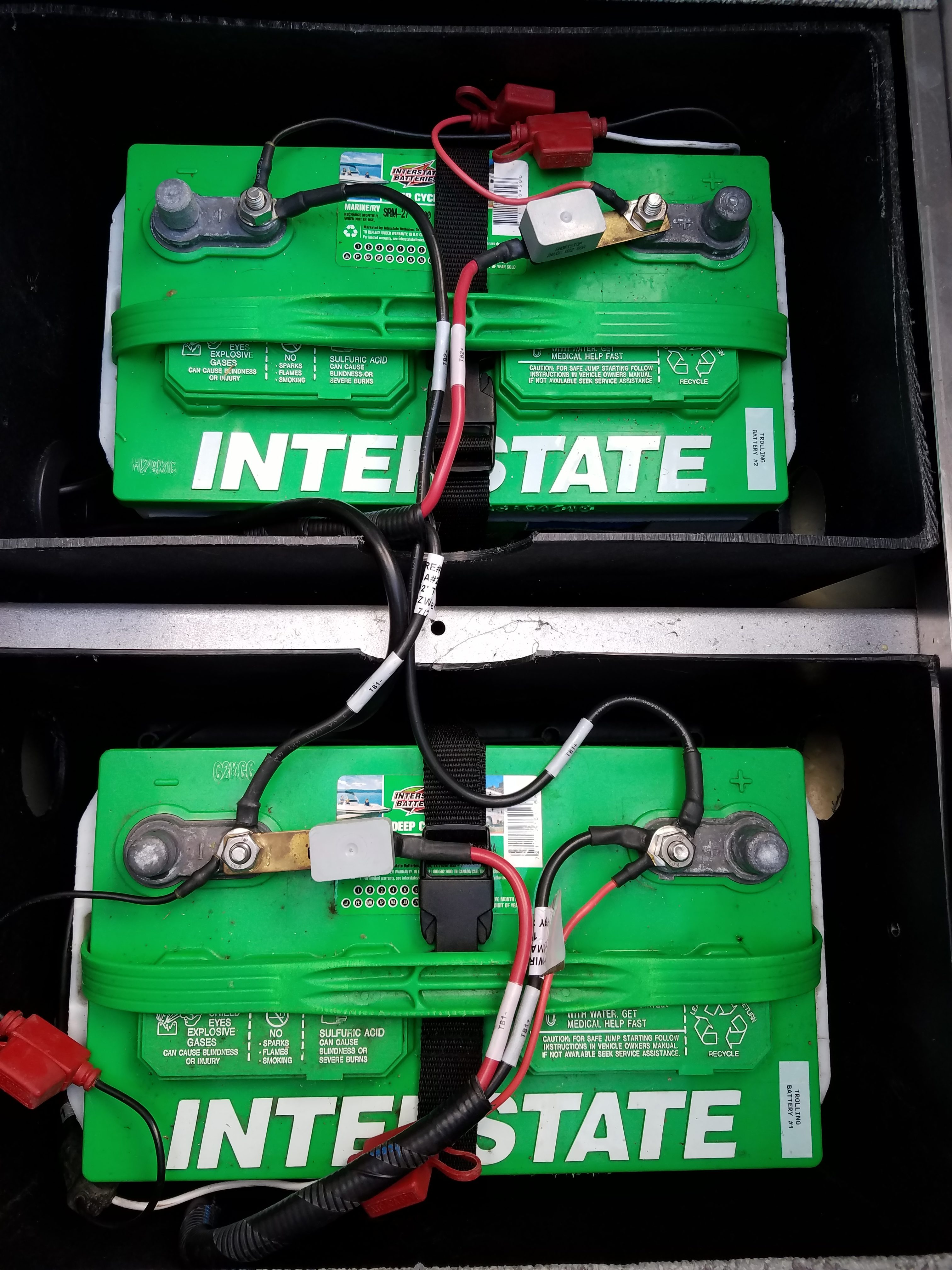
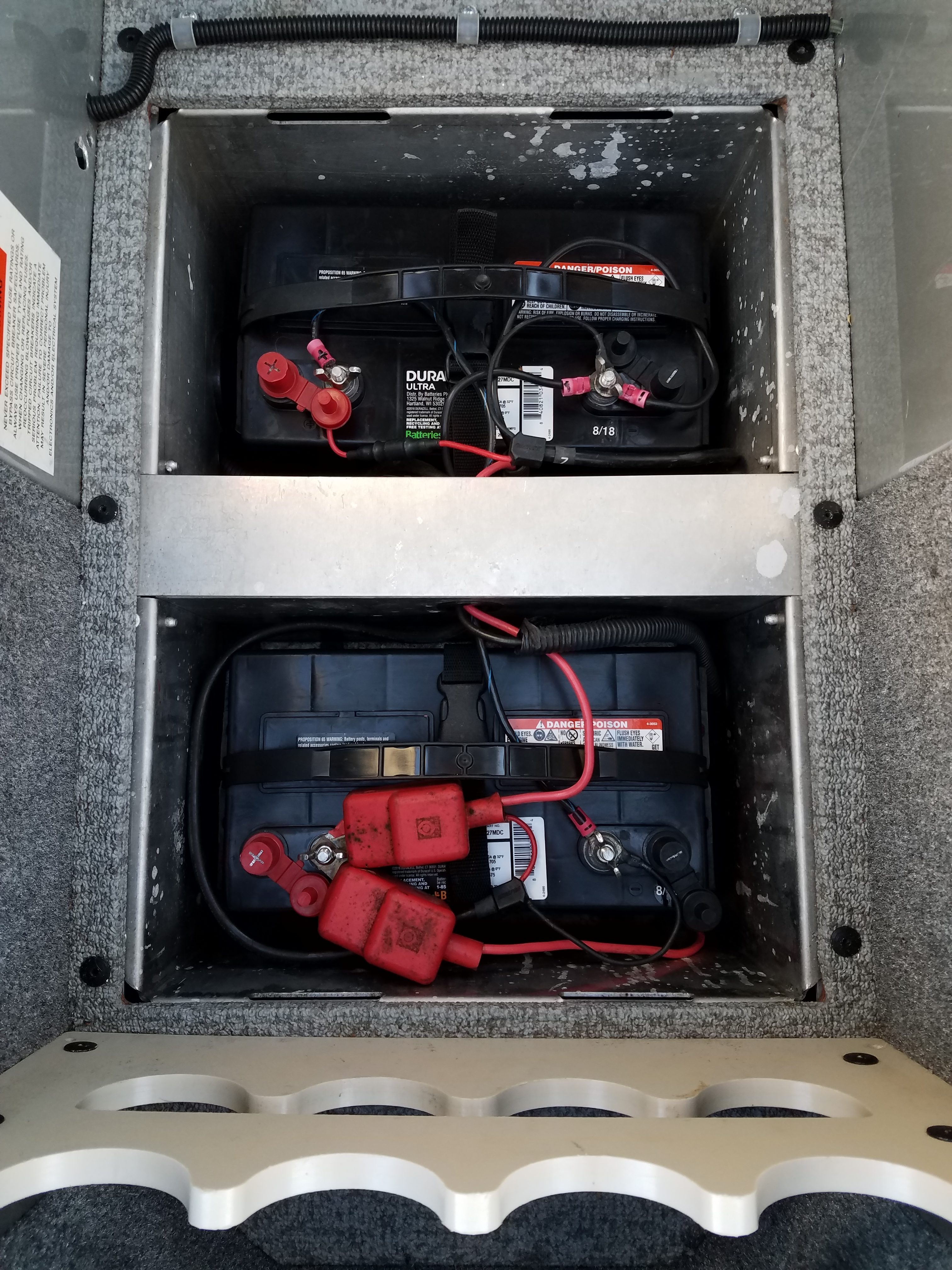
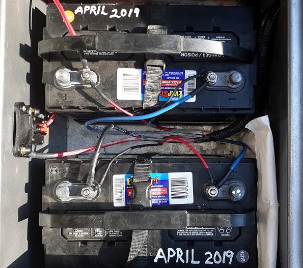
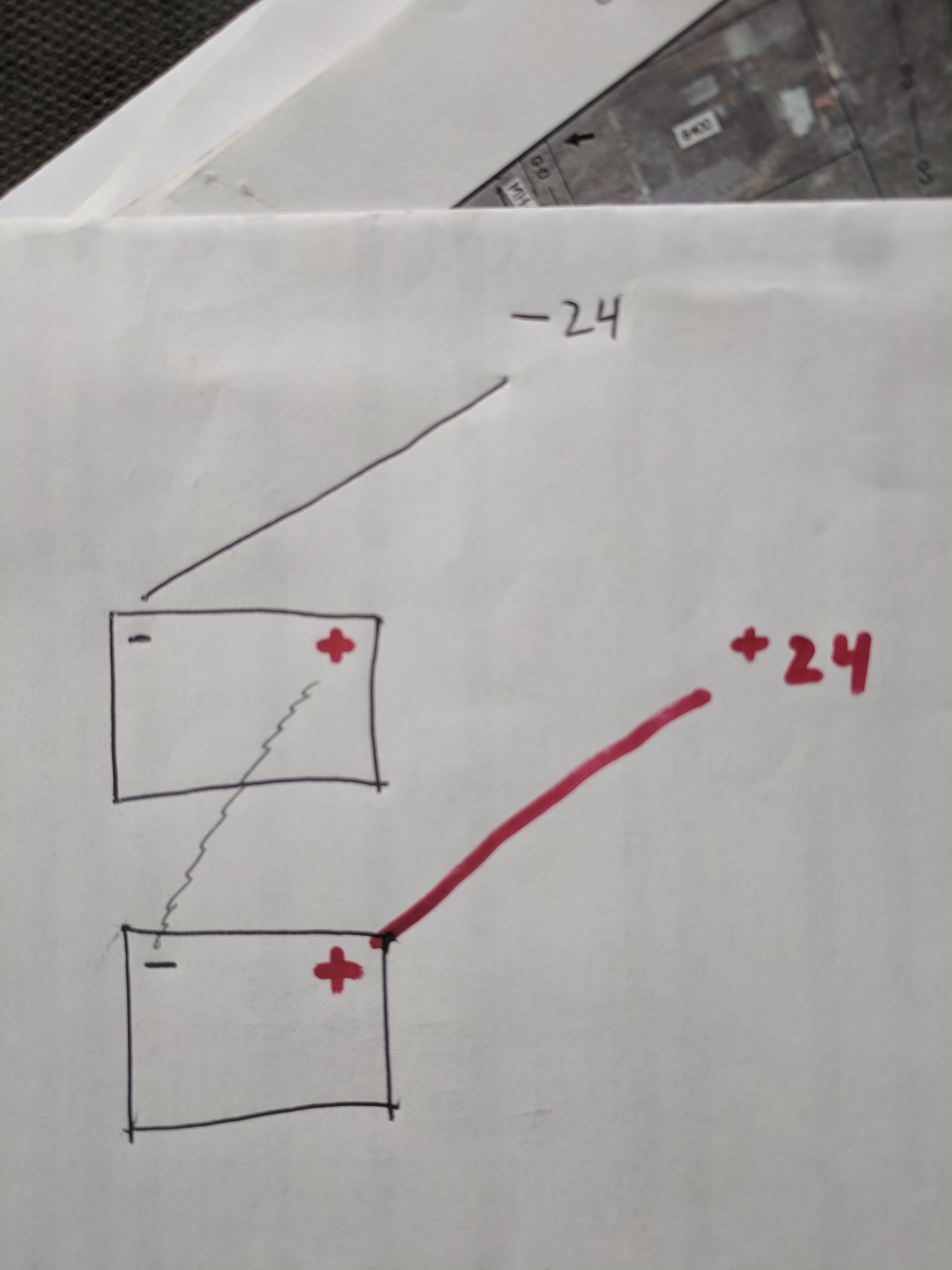
Hope you can tell what is what from my pic but I don’t think this is what I did on my last boat. Disregard the charger wires and basically you have a jumper from – to + and then 2 red and black.
Are both these red and black from the trolling motor at bow? I can’t quite tell where they come from and never installed a 24 volt motor before but in my last boat I am pretty sure both of the reds with breakers went to one battery on the positive post.
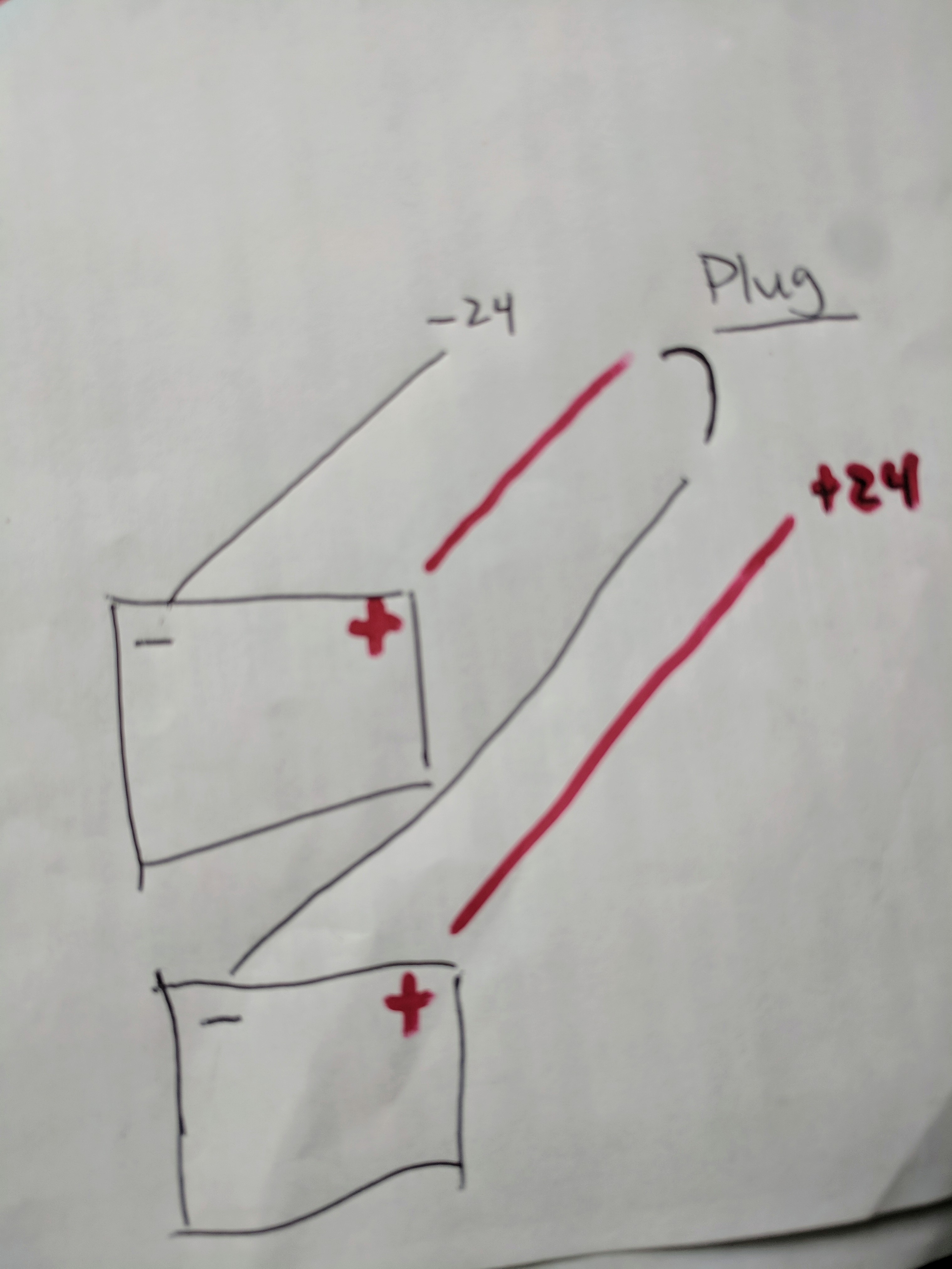
When I opened up the cover in my new to me boat, it got me totally confused. One red goes to a + post on one battery and the other goes to the – post on the other battery.
Is there more than one way to wire a motor in 24v?
Attachments:
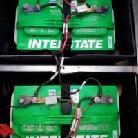
20190524_184355.jpg